


- Rubber Synchronous Belt
- Double Side Synchronous Belt
- Rubber Open Timing Belt
- Multi-wedge Belt
- Plane Belt
- Special Belt
- Special Belt 2
- Automobile Timing Belt
- PU Synchronous Belt
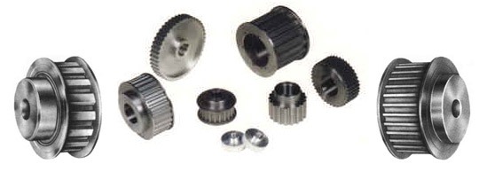
- Synchronous Pulley
- Rock.Rock Lever
- Locking Assemblies And Cone Fastening
- Single Synchronous Belt
- Double Sided Timing Belt
- Thickened Single Tooth
- Special Single Tooth
- Open Tooth
- Multi Wedge Belt
- Timing Pulley Series
- Automotive Timing Belt
- PK Multi Wedge Belt
- Rubber V Tape
- Variable-Speed Belt
- Flat Belt
- Color PU Open And Timing Belt
- Lining For Cable Car
- Cutting V Tape
- Polyurethane Synchronous Belt
- Color Rubber Synchronous Belt
- TT5 Timing Belts
- Color PU Timing Belt
- Conjoined V Belt
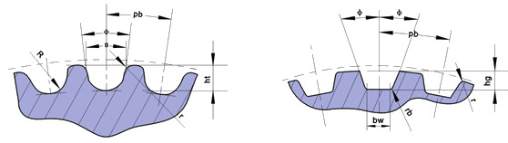
Arc tooth Timing tooth
| Slot type | Pitch pb | Deep slot hg | Slot radius R | Addendum angle r1 | Space width s | Two pitch pitch 2δ | Tooth angle |
| 3M | 3 | 1.28 | 0.91 | 0.26~0.35 | 1.90 | 0.762 | ≈14° |
| 5M | 5 | 2.16 | 1.56 | 0.48~0.52 | 3.25 | 1.144 | ≈14° |
| 8M | 8 | 3.54 | 2.57 | 0.78~0.84 | 5.35 | 1.372 | ≈14° |
| 14M | 14 | 6.20 | 4.65 | 1.36~1.50 | 9.80 | 2.794 | ≈14° |
| 20M | 20 | 8.60 | 6.84 | 1.95~2.25 |
14.80 |
4.320 | ≈14° |
Dimension of linear type pulley
| Model | MXL | XXL | XL | L | H | XH | XXH | |||||||
| Bottom width bw | 0.84±0.05 | 1.14±0.05 | 1.32±0.05 | 3.05±0.10 | 4.19±0.13 | 7.90±0.15 | 12.17±0.18 | |||||||
| Deep slot hg | 0.69 | 0 | 0.84 | 0 | 1.65 | 0 | 2.67 | 0 | 3.05 | 0 | 7.14 | 0 | 10.31 | 0 |
| -0.05 | -0.05 | -0.08 | -0.10 | -0.13 | -0.13 | -0.13 | ||||||||
| Slot width Φ+1.5° | 20 | 25 | 25 | 20 | 20 | 20 | 20 | |||||||
| Fillet radius rb | 0.35 | 0.35 | 0.41 | 1.19 | 1.60 | 1.98 | 3.96 | |||||||
| Tip radius rt | 0.13 | +0.05 | 0.30 | +0.05 | 0.64 | +0.05 | 1.17 | +0.13 | 1.60 | +0.13 | 2.39 | +0.13 | 3.18 | +0.13 |
| 0 | 0 | 0 | 0 | 0 | 0 | 0 | ||||||||
| Two pitch pitch 2β | 0.508 | 0.508 | 0.508 | 0.762 | 1.372 | 2.794 | 3.048 | |||||||
Material selection and product characteristics
The belt body used Japanese imports of high-quality synthetic chloroprene rubber, and mixed with a variety of different uses of rubber materials; skeleton materials for high quality glass fiber cord imported from Japan; with tooth surface with high elastic nylon cloth 66 protection.
The product is similar to the general synchronous belt transmission, and can be widely used in the textile, light industry, chemical industry, machine tools and other general machinery to transfer power. Customers can flexibly according to the actual needs of the length of cutting.
Related matters needing attention
1) circular arc gear is divided into single circular arc gear and double circular arc gear, the contact line strength of the single circular arc gear is higher than that of the involute gear under the same condition, but the bending strength is lower than the involute.
2) single arc gear transmission: convex teeth of the pinion tooth profile in pitch, tooth profile center at the pitch circle; gear tooth profile concave tooth in pitch, tooth profile of the center tends to pitch outside. The P1 radius of tooth profile P2 gear tooth profile radius slightly larger than the small gear tooth profile, so when the two to K, the normal line through the C node, then the tooth contact, immediately separated, but tooth profile and another end adjacent to it immediately contact, namely two K1, K gear '1, K2, K, K3, K' 2 '3...... Each point in turn along the meshing line contact. Therefore, the concave and convex tooth profile of the arc gear at any end is only used for instantaneous meshing. A new type of circular arc gear in theory is instantaneous point meshing, so the arc gear drive is often referred to as the arc point meshing gear transmission. After running gear, the actual tooth profile of high gear along with a long line of contact. Arc gear transmission characteristics are: (1) the radius of curvature is much larger than that of involute gear transmission, the contact strength ratio of involute gear transmission is about 0.5 ~ 1.5 times; (2) the rolling speed of two teeth along the meshing line direction, between the tooth surface is easy to form oil film, high transmission efficiency, can reach 0.99 to 0.995; (3) circular gear along the direction of tooth wear uniform, and easy running; (4) circular arc gear without undercut phenomenon, it is the smallest number of teeth is less. But the arc gear center distance, cutting depth and helix angle error sensitivity, the influence of three errors on the carrying capacity is large, so the arc gear high requirements on manufacturing and installation precision. In addition, the single circular arc gear tooth bending strength is weak; cutting the same modulus of large and small gear, need to use two different hob.
3) double arc gear transmission: work, to see from one end, first concave convex gear tooth drive, driven gear left, with its concave convex part to promote each other, so the double arc gear at the same time there are two contact points in theory, after running this kind of drive, there are actually two contact lines, multi tooth and multiple point meshing. In addition, because of its tooth root thickness, double arc gear, not only carrying capacity than a single arc gear transmission is about 30%, and drive more stable, less vibration and noise, the two gear and can be used in the same match on the hob processing. Therefore. In the case of high speed and heavy load, the double circular arc gear drive has the trend of replacing single circular arc gear drive.
2) arc gear using a soft tooth surface or hardened, hardened by general with the dwarf tooth.
4 (ARC) gear transmission design steps:
(1) simplified design: according to the transmission power, input speed, transmission ratio and other conditions, to determine the main parameters of the center distance, modulus. If the center distance and modulus are known, skip this step.
(2) geometric design calculation: design and calculation of the basic parameters of the gear, and the geometric size calculation.
(3) strength check: in the basic parameters, accurate tooth surface contact strength and bending strength check.
(4) if the check does not meet the strength requirements, can return.
5) procurement tips
1 the production of the company with the domestic equipment is equipped with synchronous belt, but also to replace the use of imported pulleys.
2 custom timing belt pulleys, please provide pulley drawings (figure may not have to draw the pulley tooth size), the company also can provide users with specifications, with round hole, groove, width and size for the user to draw the pulley drawings; also can provide services for surveying and mapping pulley user.
3 with the outer diameter of the wheel, the end face runout, radial runout in line with the following table 1, table 2, table 3.
4 various specifications of the timing belt selection with the tooth surface width must comply with the requirements of Table 4 below.
5 the outer diameter of the pulley and the size of the retaining wall shall be selected according to the schedule.
6 list of specifications not included in the schedule, the company can also produce.
≤ 101.60
0.10
≤ 101.60
0.13
S14M
Outer diameter tolerance of timing belt pulley(mm) Table1
Can also produce。
Pulley diameter
Tolerance
< 25.4
+ 0.050
> 25.4 ~50.80
+ 0.080
> 50.80 ~ 101.60
+ 0.100
> 101.60 ~ 177.80
+ 0.130
> 177.80 ~ 304.80
+ 0.150
> 304.80 ~508.00
+ 0.180
> 508.00
+ 0.200
Synchronous pulley(mm)表2
Can also produce。
Pulley diameter
Allowable jitter
> 101.60 ~ 254.00
> 254.00
带轮外径 × 0.001
0.25 +[(带轮外径-254.00) × 0.005]
Radial runout of synchronous belt wheel(mm) table 3
Can also produce。
Pulley diameter
Hop value
> 101.60 ~ 254.00
0.13 +[(Pulley diameter-203.20) × 0.005]
Various types of synchronous belt tooth surface width size(mm) table 4
Model
Timing belt width
Minimum actual width of synchronous belt pulley
Code
tape width
Two side pulley
Single side band pulley
Non stop pulley
MXL
012
3.0
4
5
6
019
4.8
5.8
6.8
7.8
025
6.4
7.5
8.5
9.5
XL
025
6.4
7.5
8.5
9.5
031
7.9
9
10
11
037
9.5
11
12
13
L
050
12.7
14
15.5
17
075
19.1
21
22
24
100
25.4
27
28.5
30
H
075
19.1
21
23
25
100
25.4
27
29
31
150
38.1
40
42
44
200
50.8
53
55
58
XH
200
50.8
57
60
63
300
76.2
84
87
90
400
101.6
111
114
117
XXH
200
50.8
57
61
64
300
76.2
84
88
92
400
101.6
111
115
118
500
127.0
138
142
145
T2.5
4
4
6
7
8
6
6
8
9
10
10
10
12
13
14
T5 AT5
6
6
8
9
11
10
10
12
13
15
16
16
18
20
22
25
25
27
29
31
T10
AT10
16
16
18
22
24
25
25
27
30
33
32
32
34
37
40
50
50
53
56
59
T20
AT20
32
32
35
38
40
50
50
53
56
60
75
75
78
81
85
100
100
105
108
112
3M S3M
6
6
9
10
11
9
9
12
13
14
15
15
18
19
20
5M
S4.5M S5M
9
9
12
13
14
15
15
18
19
20
25
25
28
29
30
30
30
34
36
38
8M S8M
30
30
34
36
38
40
40
44
46
48
50
50
54
56
58
85
85
90
92
94
14M
55
55
65
68
70
85
85
95
99
102
115
115
126
130
133
170
170
180
183
187
20M
70
70
80
84
89
85
85
96
100
104
115
115
127
131
134
170
170
182
185
190
230
230
245
248
254
290
290
295
300
310
340
340
355
360
370
1、Synchronous pulley type
2、Dimensions, tolerances and technical parameters
3、Various types of synchronous belt tooth surface width size table


